

Industry news
Contact information

 Phone:13828708420
 Fax:0755-29107508
 E-mail:navy@sjdtouch.com
 address:Guangming New District, Gongming City, Shenzhen third industrial zone 3, 23 floor
Industry news
Solution to the problem of electromagnetic interference of the projected capacitive touch screen
- The development of mobile handheld devices with touch screen human-machine interface is a complex design challenge, especially for projection type capacitive touch screen design, it represents the current multi touch interface technology. Projected capacitive touch screen to the position of the precise positioning of the fingers touch the screen, it through small changes in capacitance measurements to determine finger position. In this kind of touch screen application, a key design problem to be considered is the effect of electromagnetic interference (EMI) on the performance of the system. The performance degradation caused by interference may have a negative effect on the design of the touch screen, this paper will discuss and analyze these interference sources.
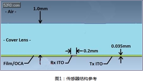
Projected capacitive touch screen structure with projected capacitive touch screen
- The typical projected capacitive sensor is mounted on a glass or plastic cover. Figure 1 shows a simplified side view of a double layer sensor. Emission (Tx) and receive (Rx) electrodes are connected to a transparent indium tin oxide (ITO), forming cross matrix, each Tx-Rx node has a characteristic capacitance. ITO Tx is located at the bottom of the ITO Rx, separated by a layer of polymer film or optical glue (OCA). As shown in figure, the direction of the Tx electrode is from left to right, and the direction of the Rx electrode is pointed out from the paper.
Sensor working principle
- Let us not consider the interference factor, to analyze the operation of the touch screen: the operator's fingers are in the ground potential. Rx through the touch screen controller circuit is kept in the ground potential, and the Tx voltage is variable. Changing the Tx voltage to the current through the Tx-Rx capacitor. A carefully balanced Rx integrated circuit, isolated and measured into the Rx of the charge, measured to the charge on behalf of the connected Tx and Rx".
Sensor status: no touch
- Figure 2 shows no touch state of the magnetic line diagram. In the absence of finger touching, Tx-Rx lines occupy considerable space inside the cover. Besides, the edge lines onto the electrode structure. Therefore, the term "projected capacitive" which comes from it.

Sensor status: touch
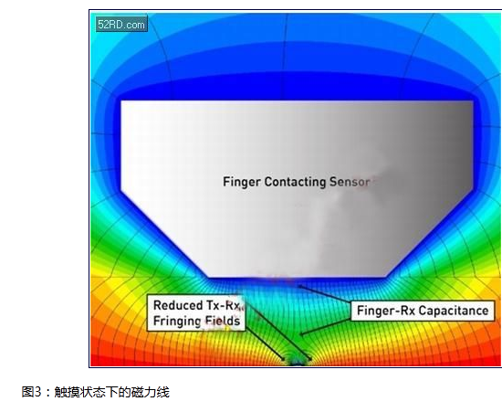
- When a finger is touching the cover plate and between the fingers and TX magnetic flux is formed, the field lines replaced the large number of TX RX fringe magnetic field, as shown in Figure 3. In this way, finger touch reduces the Tx-Rx mutual capacitance. The charge change capacitance measurement circuit identification (C), which detects the Tx-Rx node at the top of the finger. By delta C measured by all intersection points of Tx-Rx matrix, the touch points layout can be obtained by the entire panel.
- Figure 3 shows another important effect: the coupling between the finger and the Rx electrode. Through this path, the electrical disturbance may be coupled to the Rx. Certain levels of finger -Rx coupling are inevitable.
Special terms
- The interference of projected capacitive touch screen is generated by the non - easy to detect parasitic path. The term "ground" is usually used to refer to a reference node of a DC circuit and can be used to refer to a low impedance connection to the ground: the two are not the same terms. In fact, for the portable touch screen device, this difference is the fundamental reason for the interference caused by touching. To clarify and avoid confusion, we use the following terms to evaluate the touch screen.
- . Earth (ground): connected with the earth, for example, the ground wire is connected to the ground by a 3 hole AC power outlet.
- . Earth Distributed (distributed): an object to the earth's capacitive connection.
- . Ground DC (DC): DC reference node for portable devices.
- . Power DC (DC power supply): battery voltage of portable device. Or output voltage with a portable device, such as the Vbus USB in the 5V interface charger.
- . VCC DC (DC VCC power supply): power supply for portable devices (including LCD and touch screen controller).
- . Neutral (zero line): AC power supply circuit (nominal)。
- . Hot (wire): AC power supply voltage, relative zero line power.
- Vcom LCD is coupled to the touch screen receiving line
- Portable device touch screen can be directly mounted to the LCD display. In the typical LCD architecture, the liquid crystal material is provided by a transparent upper and lower electrode. The plurality of single pixels of the display screen are determined by the public electrode of the upper side of the display screen. The common electrode is a continuous plane which covers the entire visual front end of the display screen. It is biased in the voltage Vcom. In typical low-voltage portable devices (such as mobile phones), the AC Vcom voltage is between the DC and 3.3V and the shock back and forth between the Fang Bo. AC Vcom level is usually performed by each display line, so the Vcom frequency is 1/2. A typical portable device for the exchange of Vcom frequency may be 15kHz. Figure 4 Schematic diagram of the Vcom LCD voltage coupling to the touch screen.
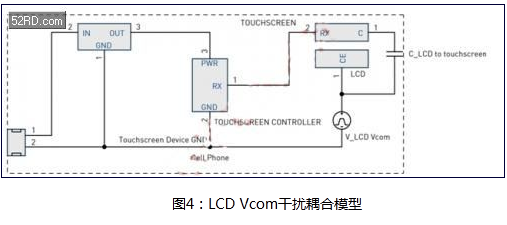
- The double touch screen is composed of ITO array and Rx array, which is separated by the Tx layer. The Tx line occupies the entire width of the Tx array, and the minimum distance between the line and the line is separated only by the minimum spacing needed. This architecture is called self shielded, because the Tx array will be shielded from the Rx array with Vcom LCD. However, through the Tx band gap, the coupling may still occur.
- In order to reduce the cost of the structure and get a better transparency, single touch screen Tx and Rx array is installed on a single ITO layer, and through a separate bridge to cross each array. Therefore, the Tx array can not form a shield layer between the Vcom LCD plane and the sensor Rx electrode. This is likely to have serious Vcom interference coupling.
- On a:Projected capacitive screen lights up the panel manufacturers enthusiasm
- Next article:Anne: Zhejiang CEO capacitance screen facing money Chein way the price collapse, there is still the prospect of a resistive screen